
服务电话:
15632773869


SIJIN PIPING 标识说明 Marking And Instructions
| SIJIN 法兰 FLANGE | |||||||||
| |||||||||
| 项目 | 厂商 | 执行标准 | 法兰形式 | 密封面 | 规格 | 压力等级 | 材质 | 热处理 | 炉号 |
| Example | SIJIN | ASME B 16.5 | WN | RTJ | NPS24 | 900LB | SA105M | N | LV0803165 |
| SIJIN PIPING 锻造管件 FORGED PIPE FITTING | |||||||||
| |||||||||
| 项目 | 厂商 | 执行标准 | 名称 | 对接面 | 规格 | 压力等级 | 材质 | 热处理 | 炉号 |
| Examples | SIJIN | ASME B 16.11 | WELDOLET | SW | NPS2 | 3000LB | A350-LF2 | Q+T | AL769 |
| SIJIN PIPING 管件 PIPE FITTING | |||||||||
| |||||||||
| 项目 | 厂商 | 执行标准 | 名称 | 端口形式 | 规格 | 压力等级 | 材质 | 热处理 | 炉号 |
| Example | SIJIN | ASME B 16.9 | FITTING | BE | NPS18 | SCH40 | A234WPB | N | H3245 |
| SIJIN PIPING 钢管 STEEL PIPE | |||||||||
| |||||||||
| 项目 | 厂商 | 执行标准 | 名称 | 端口形式 | 规格 | 压力等级 | 材质 | 热处理 | 炉号 |
| Example | SIJIN | API 5L | PIPE | BE & PE | NPS18 | SCH40 | GR.B | N | H3245 |
1、碳钢使用低应力字头压制.Carbon steel is with low stress letter pressing technique
2、不锈钢优先选用电腐蚀钢印。 Stainless steel is preferred choose electric corrosion marks
3、小于 NPS2 以下产品有选择的打制以上项目。 The flange has the above two choices for Less than NPS2
4、钢管打标方式为喷标。The pipe marking is paint
We will never use false material to replace, never maliciously demand a lower price. all material will be detected of every batch of products
before leaving factory .

| How to Inquiry a Flange | |
| ½” - 24” – covered by ANSI B16.5 | Slip-Ons larger than 24” |
| Quantity | Industry Standard 125LW, 125/150, Class 250 |
| Size (nominal pipe size) | Boiler Code Class 75, 175, 350 |
| Pressure Class (150-2500) | B16.47 Ser A dimensions per Tube Turn |
| Facing (RF, FF, RTJ, ect.) | B16.47 Ser B dimensions with 1” hub (slightly tapered) |
| Type (WN, SO, Threaded, Blind, SW, LJ) | e.g. 30" 150# RFSO Series A per TT A105 |
| Facing (RF, FF, RTJ, ect.) | |
| Type (WN, SO, Threaded, Blind, SW, LJ) | 26"-60" covered by ANSI B16.47- WN and Blinds only |
| Bore (if SW or WN) | Quantity |
| Material | Size (nominal pipe size) |
| e.g. 2 – 4” 300# RFWN STD 304 | Pressure Class |
| Facing | |
| AWWA Flanges | Type |
| Quantity | Bore (WN) |
| Size (nominal pipe size | Series |
| Class (B,D,E,F) | Material |
| Type (ring, hub, blind) | e.g. 2 - 36" 300# RF Blind Ser A 304 |
| Material (if not standard steel) | |
| e.g. 3 - 30" Class D Ring 316 | |

| 注:此文件属于麦克管道&思进管道机密,未经许可不得用于其它用途以及进行的全部或部分复制. | |||||||||
| NOTE:This document contains information proprietary and confidential to SIJIN PIPING & MIKEPIPING company ,and may not be used for purposes other than that for which it was originally furnish ,nor reproduced in whole or part except with prior written consent of SIJIN PIPING company. | |||||||||
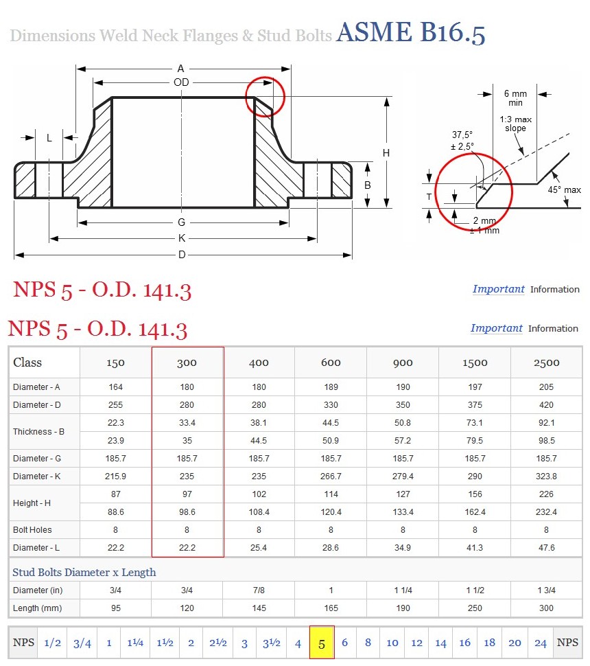
| 设计 | 工艺确认 | WN FLANGE | SIJIN-20131022-12 DN125-CL300 | ||||||
| 校对 | 质量确认 | 标准 | 数量 | 重量kg | 比例 | ||||
| 审核 | 批准 | ASME B16.5 | 12 | 16 | 1:18 | ||||
| SS F316 | |||||||||
| 日期 | 2013年10月22日 | ||||||||
| STS | MATERIAL FOR FLANGES | |||||||||
| ASTM-DIN-BS | ||||||||||
| Mechanical Values | Chemical Analysis | |||||||||
| TENSILE | YIELD | ELONGA- | C | Si | Mn | P | S | Mo | Cr | |
| STRENGTH | STRENGTH | TION | ||||||||
| Materials | N/MM2 | N/MM2 | % MIN. | % | % | % | % | % | % | % |
| ST37.2 | 340-470 | 235 | 24 | max0.17 | 0.05 | 0.05 | ||||
| ST 52-3 | 490-630 | 355 | 20 | max0.20 | max0.55 | max1.6 | 0.04 | 0.04 | ||
| ST E 355 | 490-630 | 315 | 27 | max0.20 | 0.10-0.50 | 0.90-1.6 | 0.035 | 0.03 | ||
| C21 | 480-630 | 250 | 20 | 0.18-0.23 | 0.15-0.35 | 0.80-135 | 0.035 | 0.03 | ||
| C22 | 400-550 | 230 | 27 | 0.17-0.24 | max0.40 | 0.30-0.60 | 0.045 | 0.045 | ||
| C22.3 | 410-540 | 240 | 25 | 0.18-0.23 | 0.15-0.3 | 0.40-0.90 | 0.035 | 0.03 | max0.30 | |
| C22.8 | 410-540 | 240 | 25 | 0.18-0.23 | 0.15-0.35 | 0.40-0.90 | 0.035 | 0.03 | max0.30 | |
| TT ST.35 | 390-490 | 235 | 23 | max0.17 | max0.35 | min0.40 | 0.045 | 0.045 | ||
| TTST 41 | 440-540 | 265 | 21 | max0.20 | max0.35 | min0.45 | 0.045 | 0.045 | ||
| 10NI 14 | 440-640 | 345 | 20 | max0.12 | 0.10-0.35 | 0.30-0.60 | 0.035 | 0.035 | ||
| 15 Mo 3 | 440-570 | 265 | 21 | 0.12-0.22 | 0.10-0.35 | 0.40-0.80 | 0.035 | 0.03 | 0.25-0.35 | |
| 13Cr Mo 44 | 440-590 | 285 | 18 | 0.10-0.18 | 0.10-0.35 | 0.40-0.70 | 0.035 | 0.03 | 0.40-0.80 | 0.80-1.15 |
| 10Cr Mo 910 | 445-590 | 295 | 20 | max0.15 | 0.15-0.50 | 0.40-0.60 | 0.04 | 0.04 | 0.90-1.10 | 2.00-2.50 |
| 12Cr Mo 195 | 520-640 | 274 | 20 | max0.15 | 0.30-0.50 | 0.30-0.60 | 0.03 | 0.03 | 0.45-0.65 | 4.00-6.00 |
| A105 | min 485 | 250 | 22 | max0.35 | max0.35 | 0.60-1.05 | 0.04 | 0.05 | ||
| A181 Class 60 | min 415 | 205 | 22 | max0.35 | max0.35 | max1.10 | 0.05 | 0.05 | ||
| A181 Class 70 | min 485 | 250 | 18 | max0.35 | max0.35 | max1.10 | 0.05 | 0.05 | ||
| A182 Gr.F1 | min 485 | 275 | 20 | max0.28 | max0.35 | 0.60-0.90 | 0.045 | 0.045 | 0.44-0.65 | |
| A182 Gr.F5 | min 485 | 275 | 20 | max0.15 | max0.35 | 0.30-0.60 | 0.03 | 0.03 | 0.44-0.65 | 4.00-6.00 |
| A182 Gr.F11 | min 485 | 275 | 20 | 0.10-0.20 | max0.50 | 0.30-0.80 | 0.04 | 0.04 | 0.44-0.65 | 1.00-1.50 |
| A182 Gr.F12 | min 485 | 275 | 20 | 0.10-0.20 | 0.50-1.00 | 0.30-0.80 | 0.04 | 0.04 | 0.44-0.65 | 0.80-1.25 |
| A182 Gr.F22 | min 517 | 310 | 20 | max0.15 | 0.10-0.60 | 0.30-0.60 | 0.04 | 0.04 | 0.87-1.13 | 2.00-2.50 |
| A350Gr LF1 | 414-586 | 205 | 25 | max0.30 | max0.50 | 0.75-1.35 | 0.035 | 0.04 | ||
| A350Gr LF2 | 485-655 | 250 | 22 | max0.30 | 0.15-0.30 | max1.35 | 0.035 | 0.04 | ||
| A350Gr LF3 | 485-655 | 259 | 22 | max0.20 | 0.15-0.30 | max0.90 | 0.035 | 0.04 | ||
| A694 F52 | min 455 | 360 | 20 | max0.26 | 0.20-0.35 | max1.40 | 0.04 | 0.05 | ||
| BS1503 221 410 | 410-530 | 205 | 20 | max0.20 | 0.15-0.35 | 0.80-1.20 | 0.04 | 0.04 | ||
| BS1503 221 430 | 430-550 | 215 | 19 | max0.20 | 0.10-0.40 | 0.80-1.40 | 0.04 | 0.04 | ||
| BS1503 221 490 | 490-610 | 255 | 16 | max0.25 | 0.10-0.40 | 0.90-1.70 | 0.04 | 0.04 | ||
| BS1503 223 410 | 410-530 | 230 | 20 | max0.20 | 0.10-0.40 | 0.80-1.20 | 0.04 | 0.04 | ||
| BS1503 223 490 | 490-610 | 295 | 16 | max0.25 | 0.10-0.40 | 0.90-1.70 | 0.04 | 0.04 | ||
| BS1503 503 490 | 490-640 | 300 | 17 | max0.15 | 0.15-0.40 | max0.80 | 0.025 | 0.02 | ||
| BS1503 620 440 | 440-590 | 265 | 19 | max0.18 | 0.15-0.40 | 0.40-0.70 | 0.04 | 0.04 | 0.45-0.65 | 0.85-1.15 |
| BS1503 621 460 | 460-610 | 275 | 18 | max0.18 | 0.15-0.40 | 0.40-0.70 | 0.04 | 0.04 | 0.45-0.65 | 1.10-1.40 |
| BS1503 622 490 | 490-640 | 275 | 18 | max0.15 | 0.15-0.40 | 0.40-0.70 | 0.04 | 0.04 | 0.90-1.20 | 2.00-2.50 |
| BS1503 625 250 | 520-670 | 365 | 18 | max0.15 | 0.15-0.40 | 0.30-0.80 | 0.04 | 0.04 | 0.45-0.65 | 4.00-6.00 |
STANDARD FINISH
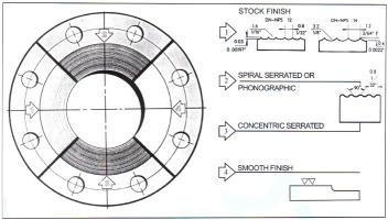
STANDARD FINISHES for Face of Fiange [ANSI B16.5]

| STOCK FINISH: | the most used of any gasker finish,becouse,practically,is suitable for all ordinary service conditios |
| ,this is a continuous spiral groove.Flange size 12"(304.8mm)and smaller,are produced with a 1/16" | |
| round-nosed tool at a feed of 1/32"per revolution.For size 14"(355.6mm)and larger. | |
| the finish is made'with 1/8"round-nosed tool at a feedof 3/64"per revolution. |
SPIRAL;SERRATED OR PHONOGRAPHOC:This finish is produced by using a90 round-nosed tool.
STOCK FINISH:
the most used of any gasker finish,becouse,practically,is suitable for all ordinary service conditios
,this is a continuous spiral groove.Flange size 12"(304.8mm)and smaller,are produced with a 1/16"
'round-nosed tool at a feed of 1/32"per revolution.For size 14"(355.6mm)and larger.
the finish is made'with 1/8"round-nosed tool at a feedof 3/64"per revolution.
SPIRAL;SERRATED OR PHONOGRAPHOC:This finish is produced by using a90 round-nosed tool.
CONCENTRIC SERRATED:this finish a prodiced by using a 90 round-nosed tool.
SMOOTH FINISH:
the cutting tool employed shall have a approximate 0.06" radius.
the resultant surface finish shall have 125 µ inch to 250uinch (ANSI B16.5 para6.4;4.1)
1.RAISED FACE,AND LARGE MAKE AND FEMALE
Either a serrated-concentric or serrated-spiral finish having from 34 to 64 grooves per inch is used.
The cutting tool employed has an approximate 0.06in.radius.The resultant surface finish shall have a 125 µ inch (3.2 µm)to 500 µ inch (12.5 µm) approximate roughness.
2.TOUGUE AND GROOVE,AND SMALL MALE AND FEEMALE
The gasket contact surface does not exceed 125 µin (3.2 µm) roughness.
3.RING JOINT
The inside wall surface of gasket groove does not exceed 63 µin.(1.6 µm) roughness.
4.BLIND
Blind flanges need not be faced in the center if,when this center part is raised,its diameter is at leastl in.smalled than the inside diameter of fittings of the corresponding pressure class.when the center part is depressed. Its diameter is not greater than the inside diameter of the corresponding pressure class fittings.maching of the depressed center is not required.


